Film grain synthesis in AV1
Published Nov. 3, 2019, updated Dec. 18, 2019.
This page describes the film grain synthesis as defined in the AV1 film grain tool. Recently, there have been a lot of question on the film grain in AV1. Hopefully, this page can answer some of them. If you would like to get more information, you can follow links on this page or contact me directly.
Motivation to preserve film grain
Film grain is widely present in movies and TV shows. In movies, film grain is part of the creative intent. Movie directors or DPs may have spent significant amount of time choosing the film grain to be used in their movie or TV-show. In the past, they might have studied samples of film stock. Nowadays, when digital cameras are used, film grain may be added in post-production.
Sometimes, camera sensor noise creates a similar effect. In all these cases, film grain or noise is present in the source on purpose, and the task of a video compression engineer is to preserve the original creative intent.
Difficulties encoding film grain
A question some people ask regarding the film grain modeling is whether it would be better to preserve the exact original grain in the source rather than modeling and synthesizing it. The correct answer to this question is that often the choice is not between the original film grain and the synthesized one. When video is transmitted over a channel with limited bandwidth, the choice is often between not having the film grain at all (or having the grain significantly distorted by compression) and having synthesized grain that looks subjectively similar to the original one.
Video compression is based on spatial and temporal prediction. Film grain shows high degree of randomness in both spatial and temporal dimensions. This randomness of the grain makes its prediction difficult. Another compression technique used in video codecs is energy compaction by transforms, where most of the residual block energy is concentrated in the lower frequency coefficients. Since grain contains a lot of high frequencies, higher frequency coefficients after a transformation (such as DCT) may have high values and will likely remain non-zero after quantization. If they are nevertheless quantized to zero, the original film grain is distorted or gone.
Furthermore, some coding tools, such as de-ringing filters, may additionally suppress film grain. For these reasons, preserving film grain may require prohibitively high bandwidth, not available when a video is streamed or broadcast.
AV1 approach to film grain compression
A better result in preserving film grain may be achieved by detecting the grain, denoising the source video, and estimating the film grain parameters from flat regions of the difference between the noisy and de-noised versions of the video sequence. The grain is later synthesized from the parameters estimated at the encoder and sent in the video bitstream. The film grain tool in AV1 works as explained in Fig. 2.

It is worth mentioning that optional film grain SEI messages exist in H.264 and H.265 video compression standards. The problem with those SEI messages is that, being optional, they are not supported by majority of H.264 and H.265/HEVC decoders, which makes it impossible to rely on them when encoding a video for distribution over wide decoder population.
AV1 video codec, on the other hand, specifies mandatory support of the film grain synthesis tool. The film grain synthesis tool supports a range of different noise characteristics, varying from film grain to sensor noise and compressed sensor noise. Additionally, the tool supports flexible modeling of the relationship between film grain strength and signal intensity.
Film grain parameters estimation
Estimating film grain parameters is an extensive topic in its own. Typically, film grain is estimated from flat regions of the difference between the noisy and de-noised versions of a video sequence. Obviously, the quality of denoising plays a critical role here. In general, adaptive video denoising using some sort of motion compensation is a good choice. Estimation of film grain/noise parameters should be based on smooth regions of the picture since high frequency components from edges and textures can adversely affect estimation of the grain parameters.
Smooth areas can be found by applying an edge detector to the denoised image followed by an optional dilation operation. The thresholds in the detector should be properly chosen to account for the local luminance changes and video characteristics. Fig. 3 shows a map that was obtained when estimating grain parameters. White areas in the figure are excluded from the grain parameters modeling.

Modeling film grain
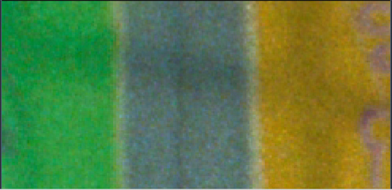
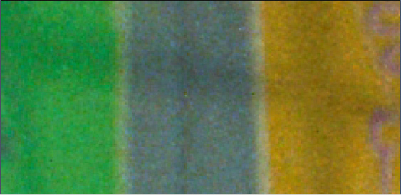
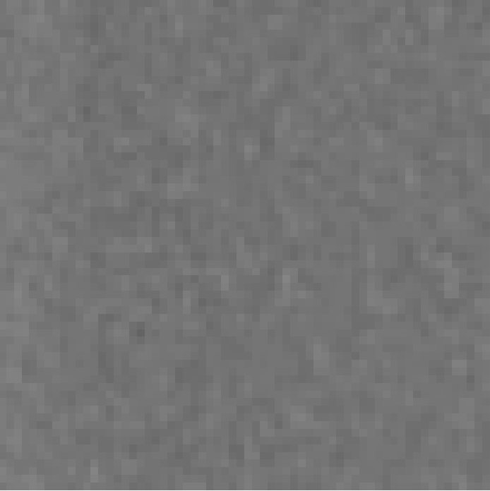
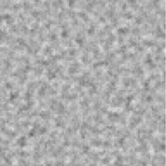
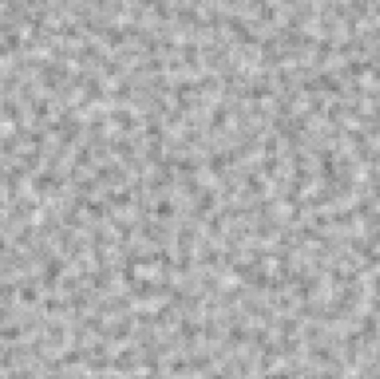
Two characteristics of the film grain important for its subjective perception are grain intensity and grain pattern. Fig. 4. shows an example of film grain with different patterns and similar grain strength (variance).
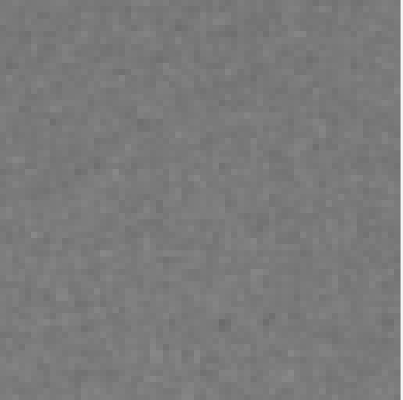
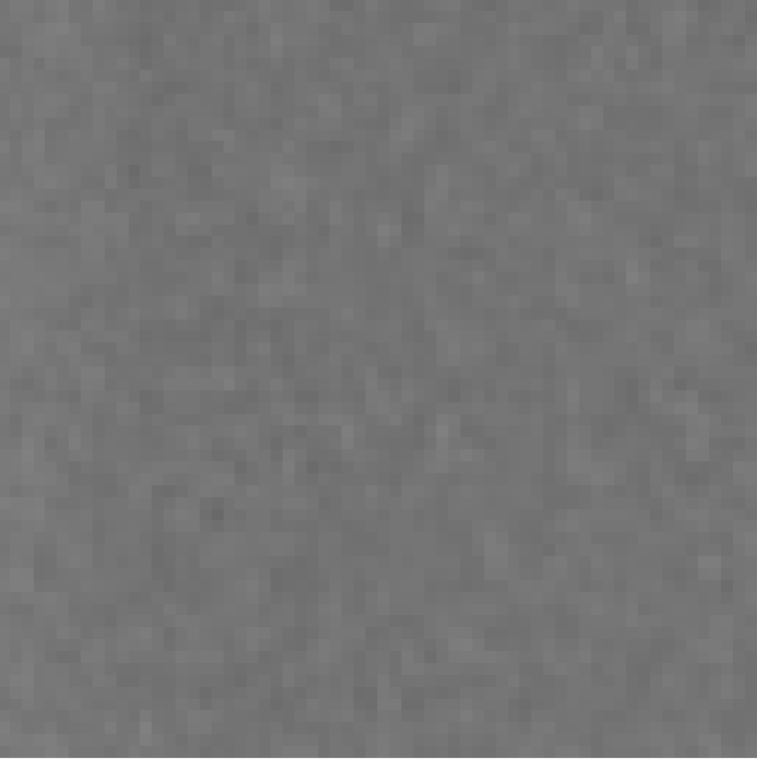
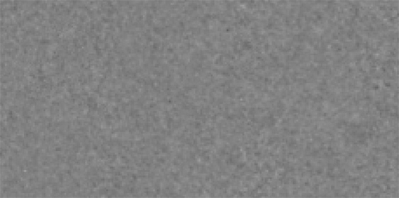
Fig. 5. shows samples of film grain with different strength while the grain pattern is the same.
There are other characteristics of the film grain that need to be modeled, such as correlation of grain between color channels. In film, grain is often said to be independent between R,G, and B channels and proportional to the linear light intensity. After a YCbCr color transformation, grain between the channels is typically correlated. Application of the film grain in AV1 is made in the coding (e.g. YCbCr) domain to make processing feasible in the decoders. Correlation of grain between color components has to be captured during the film grain estimation.
The rest of this section discusses modeling of different aspects of film grain.
Pattern modeling
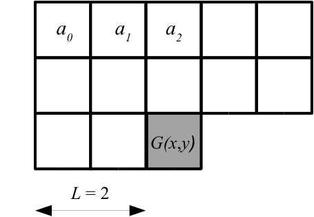
The film grain pattern in AV1 is modeled by an autoregressive (AR) process. An example of AR modeling is shown in Fig. 6. The value of the current grain sample (gray square) is modeled as a weighted sum of the previous grain values in a 2D causal neighborhood (white squares) and a Gaussian noise sample. In Fig. 6, a parameter lag L equal to 2 is used. The lag defines the size of the grain sample neighborhood used in the AR model. AV1 supports lag values from 0 to 3.
Mathematically, it can be expressed as follows. Let G(x, y) be a zero-mean normalized grain sample at position (x, y).
G(x, y) = a0*G(x − 2, y − 2) + a1*G(x − 1, y − 2) + a2*G(x, y − 2) + ... + z,
where a0, ..., aN are AR coefficients, and z is a unit variance pseudo-random Gaussian noise.
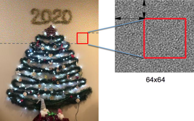
This is equivalent to performing IIR filtering of a block of WGN samples in a raster scan order. In this way, three film grain templates are generated:
- 64x64 template for Y (requires 4K memory for 8-bit data)
- 32x32 templates for Cb and Cr in 4:2:0 video (requires 1K memory each for 8-bit data)
When the film grain is applied to the reconstructed video, these templates are used to extract a block of grain that is applied to the reconstructed frame as shown in Figs. 7 and 10. The block sizes for applying the grain are 32x32 for luma and 16x16 for chroma in 4:2:0 video. For other types of chroma subsampling, the blocks and template sizes are scaled accordingly. The offsets in the vertical and horizontal directions used for extracting the grain blocks are derived with a pseudo-random numbers generator. The generator is deterministic and initialized per frame with an initialization value signaled in the bitstream.
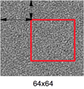
Fig. 8 shows an example of a synthesized luma film grain template (center), with original grain being on the left and the AR coefficients used in modeling on the right. The background gray color represents coefficient values equal to zero, lighter colors represent positive values and darker colors negative values.

Film grain pattern in chroma components is modeled similarly to luma except that there is also an AR coefficient that captures correlation between chroma and luma grain.
Intensity modeling
As mentioned above, AV1 film grain is modeled in the transformed domain, such as YCbCr since:
- Post-processing can change relationship between signal intensity and grain strength
- It is more computationally viable to model and apply grain directly in the coding domain
Y’ = Y + f ( Y ) * GL,
where Y is a reconstructed luma sample value before the film grain is applied, f ( Y ) is the piece-wise linear scaling function as in Fig. 9, and GL is the normalized film grain pattern sample at the corresponding position.
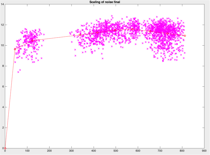
Points determining the piece-wise linear scaling function are signaled in the bitstream. The scaling process can be efficiently implemented with a LUT.
Chroma grain intensity may depend on the collocated luma intensity. For example, chroma grain in darker areas may be different from the chroma grain in lighter gray areas even when chroma intensity in these areas is similar. Therefore, the encoder can model intensity of the chroma film grain dependent on both chroma and luma intensity. More details on this modeling can be foundhere, in a DCC'2018 paper describing the AV1 film grain.
Film grain application process
Film grain is applied as follows. First, a picture is reconstructed and placed in the picture buffer where it can be further used for prediction. Pictures before applying the film grain are used for motion compensation since they are better for improved compression efficiency. When a picture is ready to be sent to display, film grain synthesis process is applied. First, film grain patterns for Y, Cb, and Cr components are generated and scaling LUTs are initialized. Then, the film grain is applied to the picture block-wise in a raster scan order as shown in Fig. 10. Each block is taken from the film grain template with pseudo-random offsets offX and offY, and added to the reconstructed frame, with samples scaled based on the scaling function described above.
The most memory efficient way to add film grain is before the picture output. However, some decoders may choose to apply the film grain in advance. In this case, an additional picture buffer needs to be allocated and pictures that need to be output (not alt-ref pictures) identified. The decoder can identify reconstructed pictures that are going to be displayed by examining the frame header flag showable_frame.
Treating film grain blocks boundaries
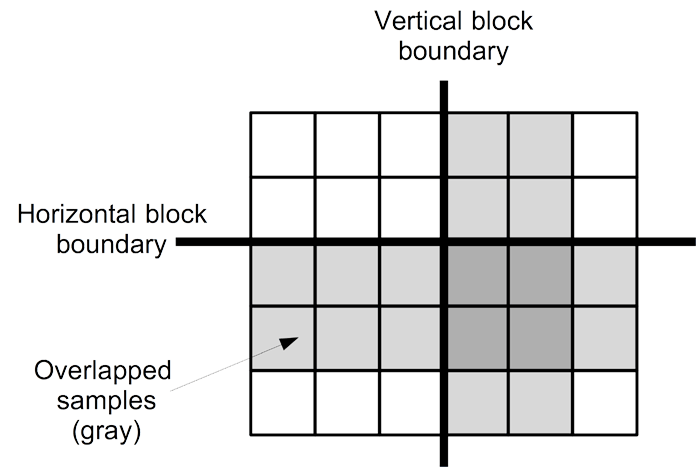
It should be mentioned that even though film grain resembles noise, some types of film grain, especially after (pre-) compression may exhibit low-pass characteristics. In these case, transitions between 32x32 grain blocks may become visible. To attenuate these transitions, film grain synthesis algorithm in AV1 can use grain blocks overlap, an optional feature that can be signaled by the encoder. This overlap is two samples wide (see Fig. 11). The overlap process is performed before adding grain to the samples. Therefore, a line buffer that is needed to keep grain blocks data from the upper row is rather small since only two 4-bit offsets offX and offY need to be stored per a 32-sample segment of the horizontal boundary. The buffer is 60 bytes for HD resolution and 120 bytes for UHD.
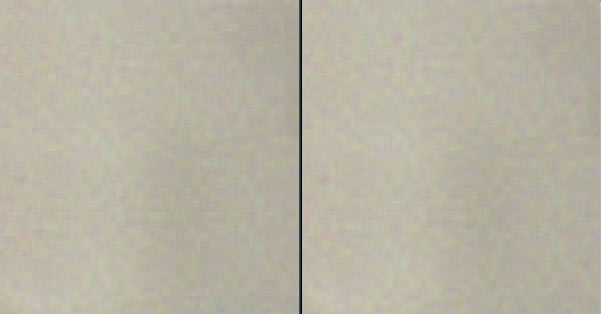
The blocks overlap attenuates artifacts on larger film grain. Fig. 12 demonstrates block artifact removal. Blocks on the left (without overlap) demonstrate some mild block artifacts. The artifacts are attenuated on the right, where block overlap is used. More details, such as weights used for overlap operation can be found in the DCC'2018 paper.
Film grain changes over time
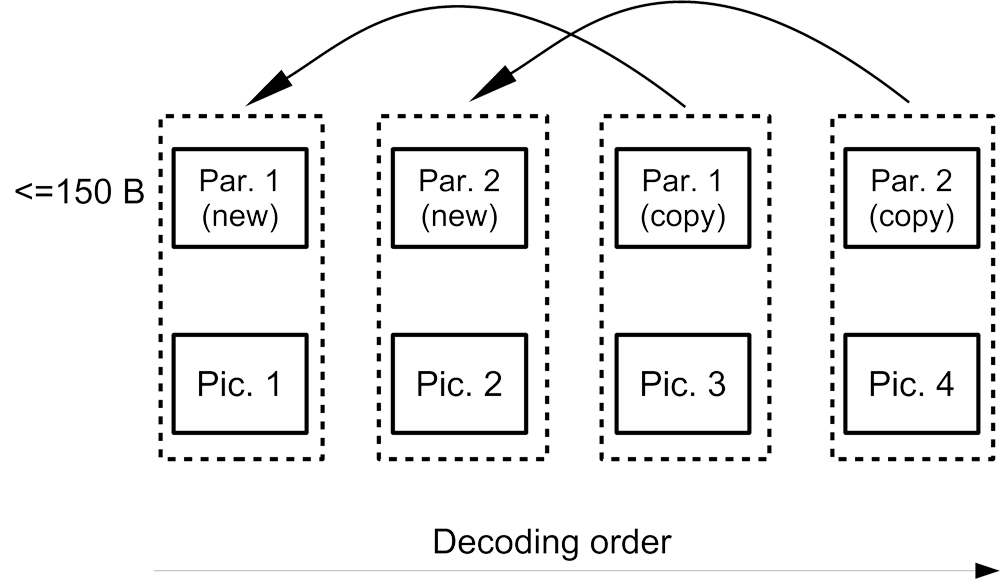
Film grain in the source video can change over time. The film grain tool in AV1 can update the grain model parameters at any frame, which allows adjusting the film grain model over time. A set of the film grain parameters can take up to 150 bytes. To reduce bitrate spent on signaling the parameters, a frame can refer to grain parameters from a previously decoded frame. This scheme is demonstrated in Fig. 13, where pictures 3 and 4 copy film grain parameters from two previously decoded frames. The restrictions for referring to the film grain parameters are the same as for reference pictures (e.g. a picture from a lower scalable layer cannot use a picture from a higher scalable layer).
Film grain conformance options
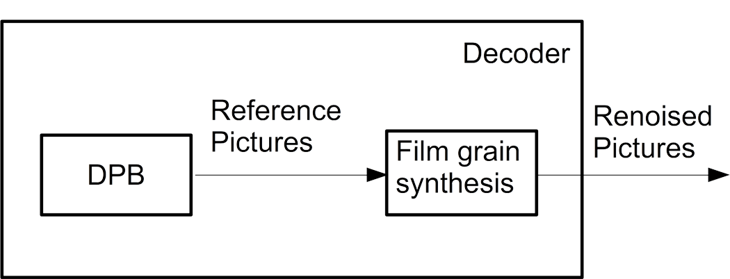
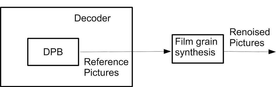
AV1 specification stipulates that a conformant AV1 decoder must support the film grain synthesis tool. The specification offers two options for a decoder to fulfil this requirement. Option 1 (see Fig. 14) may be a preferred option for a device that implements film grain inside a decoder. In this conformance option, film grain is applied directly to the reconstructed picture. The device can prove the conformance by making sure that output pictures match bit-exactly the output of the reference implementation (specification and/or reference software) after applying the film grain.
Option 2 (Fig. 15) may be a preferred option for a device that implements film grain as part of the display pipeline. This option can be used by a device that employs some post-processing steps between picture reconstruction and application of the film grain. For example, some additional deblocking / denoising may be applied to the reconstructed picture before applying the film grain. The device can prove the conformance to Option 2 by making sure that the decoder output (see Fig. 15) before applying the film grain matches bit-exactly the reference implementation output at the same stage. The film grain shall be applied to the output picture and be perceptually equivalent to the grain generated by the reference implementation. A conformant decoder shall support at least one of these two conformance options.
Effect on objective quality metrics
Film grain tool allows streaming video at a lower bitrate while providing better perceptual representation of the film grain. There is also an additional benefit of film grain masking some compression artifacts, such as banding, ringing, and blockingness. One should remember, however, that even though the subjective quality of an encode using the film grain tool may be higher, applying synthesized film grain can decrease some objective quality metrics, such as PSNR. Even though the synthesized grain can closely resemble the original grain, individual grains are likely to be located in different positions than in the original video, which results in increased MSE and correspondingly decreased PSNR. Similar reasoning can be applied to some other objective quality metrics as well. Designing objective quality metrics that capture subjective improvements from the synthesized film grain is an open research topic.
Further reading
To learn more about the film grain synthesis tool in AV1, the reader is encouraged to read our DCC 2018 paper, written with Neil Birkbeck from YouTube. The paper is complimentary to this post and contains some more technical details, as well as numerical results and subjective quality illustrations. Some part of the material in this post was presented in my talk at video@scale 2018.
AV1 specification is another source that can be used for details on the AV1 film grain algorithm. In case of further questions, readers can contact me using the information at the bottom of this page.